Updated: 21 September, 2000
This web Page has been created by Dave Munroe of Waverley, Nova Scotia, Canada, with the help of his son Don who knows more about computers than his Dad does about cars. Thanks, Don! I am also grateful to Wayne Kube, of Plano, Texas, who allowed me to steal some neat boilerplate MGB images from his MGB Art website http://web2.airmail.net/wkube/MG_Art.htm to make this site a little more attractive. Thanks, Wayne!
I have a 1974 MGB Roadster that was built by a talented previous owner from pieces and parts of more than two cars. On first inspection, it looks original, but closer examination will reveal to the enthusiast several clues to it's mixed heritage. It has 59,000 miles on the clock, and I have no clue as to the accuracy of this mileage.
It also is equipped with an overdrive unit, and the entire car is in good fit and fiddle. I have driven it approximately 15,000 miles and have spent most of my garage time with it detailing the "corners".
As it is not an original, and never can be an original, I have been freed from the need to stay with original equipment, and am not constrained from adding just about anything to my "B" that will make it more fun to drive and more interesting as an MGB hotrod...even if it will not be well recieved by the concours crowd.
I discovered Hans Pedersen's Website about 8 months ago, and was excited about the prospect of adding his well developed kit to my "B". Hans is a very friendly guy who answered all of my questions to the point that I finally had the confidence to do business with him in far off Australia. I have not been disappointed! The parts to his kit are extremely well designed and built, with several special castings that would look good in the engine bay of any state-of-the-art race car.
I have seen many interesting and whistful threads on the MGB Bulletin Board regarding applying modern supercharger technology to our LBC's. Since I now have the good fortune to be installing one on my "B", I have committed to chronical for all to see the process through this special website. Enjoy, and if you have any questions please e-mail me.
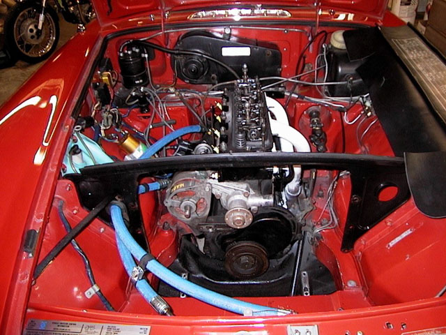
This is where you begin: the air filters, carbs, intake manifold, all vacuum lines, hoses, rad and hoses, and pulleys are removed. If you don't already have a set of big bore headers installed, now is the time. The crankshaft pulley is still on because it has to be marked and the crankshaft positioned so the new pulley can be accurately marked for TDC. (The new pulley is not marked due to the large variety of pulleys and timing strips installed on the MGB motor during it's production). Also, I couldn't get the darn thing off, even using my 30" breaker bar. More about this later.
The valve cover is off, as I took the opportunity to have the cylinder head refreshed while I was at it. It has just been re-installed.
You sharp-eyes will notice that the steering rack has been pulled forward to get at the crankshaft pulley bolt.
The trick blue hoses lead to the oil cooler. They are an oil industry specific product designed to carry high-temp high-pressure oil. I tried to get braided steel lines, but my local Aeroquip shop couldn't match the oil cooler fittings threads with their inventory, so they came up with these cool lines. I think I like 'em better anyway!
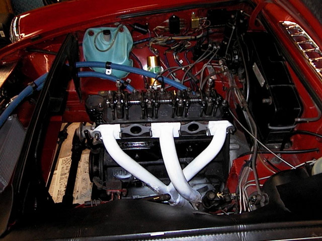
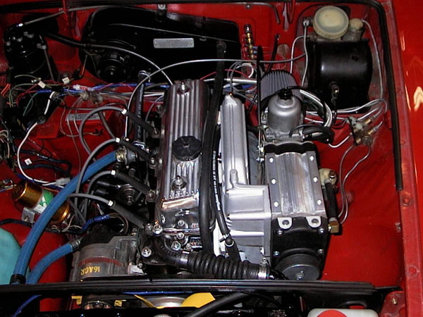
This is the the view from the "business" side of the motor. Should be easy going from here.
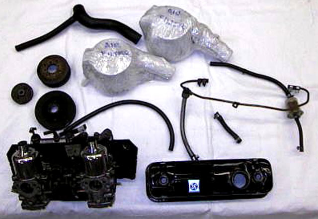
This is the pile of stuff removed for the supercharger installation.
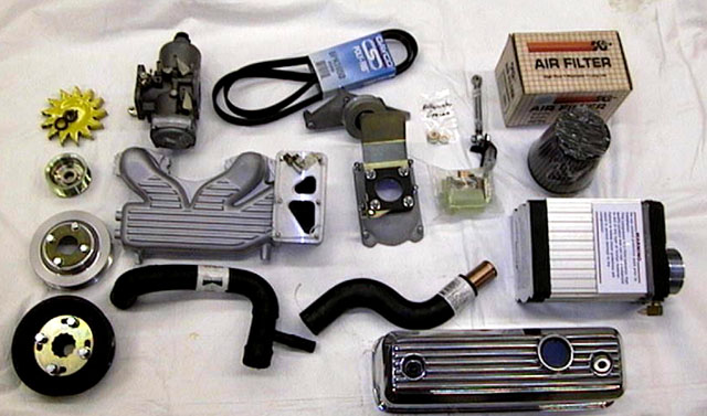
Here we have what you get for your money from Hi-Flo with your supercharger kit. In addition to these parts, you should also have,
as previously mentioned, a good set of large bore headers, an electric fan kit, and a solid motor.The alloy valve cover is not included in the kit, but available from Hans for a few extra bucks.
You will also want a Boost/Vacuum meter to fit in the cockpit. I purchased an Autometer guage at my local hot rod shop.
It is highly recommended that you access some way to measure your fuel/air ratio throughout the rev range. If a rolling road test facility is not available, a good on-board meter such as the Halmeter AF30 is a good solution.

The supplied parts are very high quality and truly beautiful. Check out this waterpump pulley and shims.
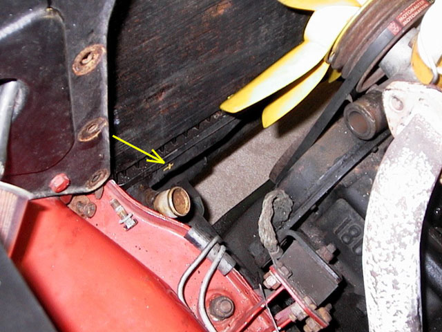
Now we begin in ernest. The radiator mods are first.This is the radiator as found in my car. The bottom tube is pointing up and is parallel to the rad. If the hose were fitted here, it would foul the new serpentine pulley and belt system. The rad needs to be modified to allow a new hose to be fitted to clear the belt, by soldering a new outlet tube on the rad where I have marked it with a yellow "X".
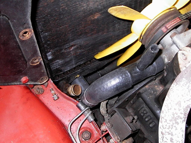
Here you can see how the new rad-to-waterpump hose fits to the lower rad tank. It wants a tube that is fitted at 90deg. to the tank in this new location. This involves removing the original tube and blanking off the hole with a plug; fitting the new tube, and while we are at it, having a proper drain valve fitted so I can drain the cooling system without covering the garage floor with coolant.
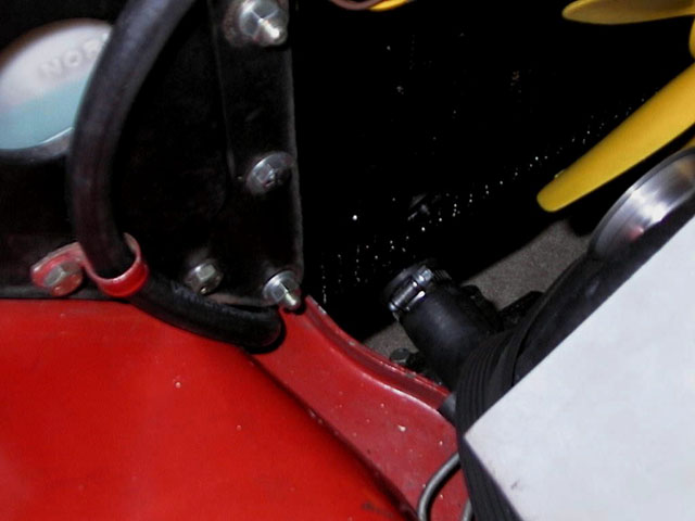
The finished rad. Long story, keep it short: original rad had been modified, installed, electric fan installed, rad leaks. Back to rad shop for new core, paint job, re-installed electric fan, back in car, finished. Thought I HAD a good rad to start with.....
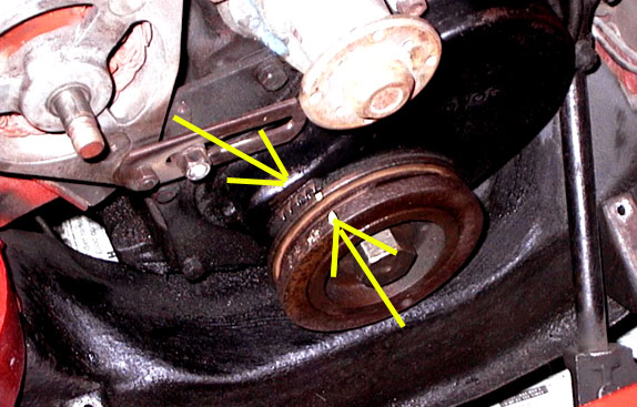
The new pulley is not marked for Top Dead Centre, so it is important to roll the #1 piston to exact TDC, make sure the timing marks line up, (painted here to make the marks easier to see), and hold everything tight while the new pulley is replaced. It can then be permanently marked to the existing timing strip on the block for accurate timing use in the future. The bolt holding on this pulley was a particularly miserable sob to remove. I had removed the cylinder head to "freshen it up", and had no good way to hold the crankshaft from turning while coming on to my 30" breaker bar with the 6 point socket on the bolt. Calls for help on our local club Bulletin Board produced no end of innovative, but alas, unsuccessful ideas. .In the end, I got a great tip from the resident wrenches at the local Motorcycle shop. I was advised to crank up the compressor to 120psi, get the socket ready on the bolt, fill my 1/2" air impact gun with ATF through the hole where the hose snaps on, and let 'er rip. With son Don on the foot brake and the tranny locked in 4th gear, I got everything ready and pulled the trigger. I swear it didn't hit the bolt twice before it broke loose and spun off that pulley! Its a great day when you get a tip like that...
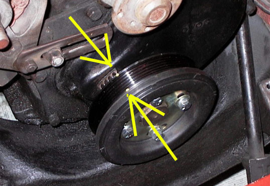
Here is the new crankshaft pulley, with integral "racing bolt lock" that I found out later fouled the steering rack, so I had to remove it. The new TDC mark has been centerpunched on and painted for clarity.
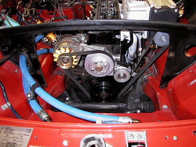
The crankshaft pulley is the"datum" for alignment with all the other pulleys, which have to be shimmed to very close tolerances. It is a tribute to the engineering quality of the specially made parts that the supercharger pulley lined up perfectly. It is attached to the cast intake manifold (opportunity 1 for misalignment) which is attached to the cylinder head (opportunity 2). The waterpump pulley came with a set of shims, used all but one; and the idler pulley, which came with its own exquisite little alloy casting, was also perfectly shimmed right out of the box. The alternator pulley was firmly mounted to the alternator, and the alternator itself was moved in its bracket with supplied washers. Too bad you couldn't drive around without the radiator and show off the neat serpentine belt drive system!
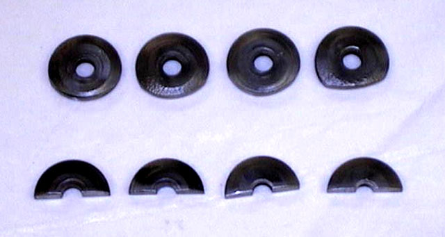
The intake manifold flanges where they bolt ont the head are quite a bit thicker than the exhaust manifold flanges, so spacers have to be made to fill in the gap. It is important to have these spacers the proper thickness,otherwise one of the two manifolds could be left slack and allowed to leak. As it turns out, the original thick manifold washers are the exact proper dimension, and cutting two of them in half and grinding the outside circumference to fit the manifold depression was the perfect solution.
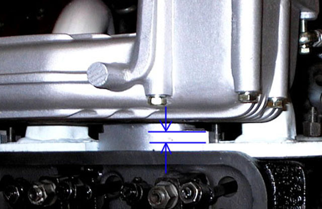
Here you can see the mis-match in the thickness of the intake and exhaust flanges where they bolt onto the head. Not a difficult task to solve, but a fairly critical dimension, none-the-less.
Now i'ts coming together. Most of the mods to the engine room have been completed, so now we were able to bolt the carb to the supercharger, and then fit the supercharger to the intake manifold.
Cables next. Small fingers are the order of the day, as the linkages are between the carb and the manifold. Not much room to work.
Hook up the fuel line, the vacuum line to the distributor, the crankcase breather hose, and the line from the charcoal cannister to the valve cover. Last is the floatbowl overflow, that needs to be taken to the other side of the motor, away from the exhaust manifold.
Starting to look good!
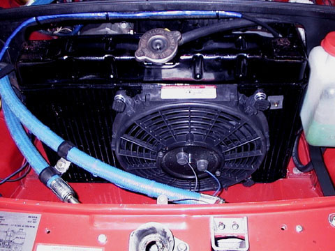
This is the 10" Hayden fan that I installed. Its about the largest you can get in there. A 180 degree sensor switch is mounted between the fins of the rad, and I wired in an override switch which is mounted on the front center consol beneath the radio.
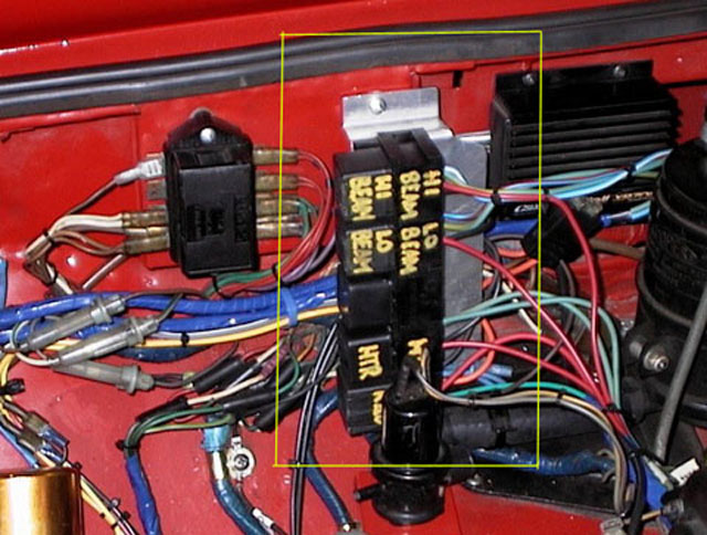
The Hayden cooling fan came with a relay, so while I had everything torn apart, and in an inspired moment, I decided to wire all the heavy electrical components through relays, as recommended by all the gurus of LBCdome. I made up an aluminum panel and mounted relay recepticals to it. It installed neatly behind the original MGB fuse block on the passenger side inner fender. (oops, excuse me....wing!).
I brought a 10 guage wire up to the engine room directly from the battery and wired it to a terminal strip, so every relay could have its own fused power supply. Made a HUGE difference to the speed of the heater fan, and the headlights have to be seen to be believed. Well worth the effort, and the $50 or so in parts that it cost.
Next the dash lights......
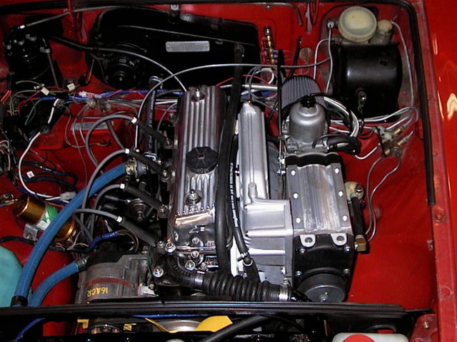
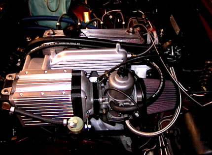
The finished look!
Fill all the fluid reservoirs, carb dash pot, prime the carb, turn the key, all while holding your breath. Surprise! It started right up, and sounded exactly like it did before it was installed. The supercharger is surprisingly quiet, and with the bonnet closed, nary a hint of what lurks beneath. As a sleeper and stealth machine - full marks. As a fire breathing monster ready to rip up the asphalt and letting the whole world know in advance, well, not.
The next phase is "Tuning". I am well into it as I write, and when I get it all sorted out I will be back with the news.
Varoom!
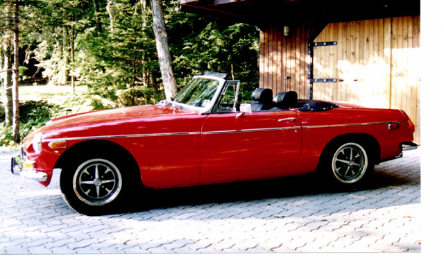
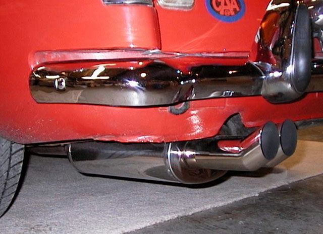
Who would believe what lurks beneath the hood of this innocent looking MGB? Maybe what's under the rear bumper will give it away.......
21 September, 2000
I am two weeks down the road from first startup, and am closing in on something approaching "good tune". But it was a rough ride.
Right off the bat I made a dumb mistake....the throttle linkage on the carb had a nipple for the cable, but the choke did not. I didn't notice this until I had the carb already on the supercharger on the car. The left side of the carb where the linkages are located is very close to the intake manifold. Too close to easily get at one of the nuts that holds on the carb.So I decided to remove the choke linkage to install a cable nipple. Of course, the linkage is under spring pressure, so when I removed the linkage, the spring unwound and I lost the index of the choke shaft which simply rotates around and around.
New expletives deleted were invented as I spent mucho time getting all of this back together. But succeed I did and everything, (I thought) was ready for initial fire up.
After everything was buttoned down, and everything I could check was checked twice, the big moment came and the key was turned.....it started right up, surprise! The guages came up, the temperature was at normal, so down the road I went for a shakedown.
My elation was short lived, as it would not take any throttle. It "felt" very lean. Back to the garage for some checks. I had made some basic errors. I assumed the carb would be set-up somewhere close, and would only need some fine tuning to make her sharp.
As it turned out, the jet was set level with the floor of the throat, where in hindsight you would expect to find it. So I backed it down 2 1/2 turns and lit out again. Not much better. But I did discover that if I pulled the choke full on, it would run like a bandit on full boost, showing about 8 psi on the guage.
So at least we knew we were running very lean. I found a source for another needle the same as the one in the carb, (a BBC: a very "rich" needle) as well as one that was quite a bit richer at the top end (the needle was thinner at the tip). I tried the latter but it turned out to be leaner than the BBC everywhere except at the top end, so it didn't work. I hadn't yet sprung for a Halmeter, and there are no rolling roads around here, so I realizied I needed to know what was going on with the mixture or risk blowing something up trying to dial this thing in by the seat of my pants.
I ordered the two needles SU make that are richer than the BBC form Burlen in England, as well as a Halmeter from California. In the meantime, I had some time to think about what was happpening. I suspected a possible air leak in the intake system somewhere, but was reluctant to remove the supercharger and manifold because I had only one set of gaskets, and they were glued onto the parts with Lock-Tite sealant.
So I played with the carb. Hans suggested I lift the needle in the piston as far as it would go, and put heavy oil in the dashpot. I also wound the jet down to richen up the needle. It wouldn't idle below 1200rpm, but it would almost run at full throttle without the choke, and was running decent from idle up to about 3/4 throttle.
Since I had two BBC needles, I could sacrifice one to some experimentation. I polished down the lower half of one with 600 wet sandpaper, to a tip thickness of .033", ( stock was .044"), and finished it with metal polish to a high gloss finish. This needle suddenly brought the thing to life. But what a radical solution. Hans said the stock BBC needle works in 90+% of all installations, so something was wrong.
I bit the bullet and dismantled the parts from the cylinderhead out.
Even after close examination, I could not see any sign of a leak. So I cleaned everything, re-assembled the works after setting the float level and the jet height in the carb, and hit the road. Well, the dang thing was now running super rich everywhere. There must have been a leak somewhere, and it was cured on re-assembly.
Back in went the stock needle, regular Damper oil, and stock jet height. Now running, by the seat of my pants, just slightly lean.
My Halmeter has arrived, and I have it partially installed. Hopefully I will get it in tomorrow and see first hand what's happening with the mixture.